
BIO340 Laboratory Guide #5
SENSORY CODING BY ACTION POTENTIALS
IN THE COCKROACH LEG
Touch, detection of substrate or water vibrations, detection of airborne vibrations (sound), monitoring of orientation and acceleration, and monitoring of changes in organ or joint position are all mediated by mechanoreceptors. A mechanoreceptor cell responds to a physical distortion with a change in membrane conductance, and hence membrane electrical potential. Such a change is translated into a change in the rate of production of action potentials in the sensory neuron(s) which service(s) the mechanoreceptor. This laboratory exercise involves monitoring activity in a peripheral nerve of a cockroach leg, in order to elucidate some of the response properties of two classes of mechanoreceptors. We will look first at the cuticular sense organs called tactile sensillae. These are located all over a cockroach's body, but are particularly large and prominent on the tibial segment of each leg. The rigid sensory spines of these organs are hinged at the base, and protrude from the cuticle. They are extremely sensitive to touch and provide helpful information to the cockroach when it is navigating tight spaces, such as between the top flaps of your breakfast cereal box. The other type of mechanoreceptor which we will investigate is the campaniform organ. These dome-shaped structures are located near the joints of each leg, and monitor joint movement and position by responding to deformations of the cuticle itself.
We will be studying these mechanoreceptors in Periplanatus americanus, the American cockroach. As the name suggests, this is a cosmopolitan species of the New World and our subjects for this experiment may have been locally (actually very locally) obtained. Besides economy, there are additional advantages to studying mechanoreceptors in cockroach legs. From a physiological point of view, a cockroach leg does not particularly care if it is still attached to the cockroach. The nerves of the leg are sealed in a relatively water-tight cuticle and remain viable long a after the leg itself is detached from the cockroach. Because the nerves can be readily seen through the cuticle, they can be electrically accessed for recording without dissection, using simple bare metal pins as electrodes. Finally, although these nerves have a large number of axons, it is relatively easy to instrument stimuli which activate only a few axons at a time.
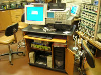
I. EQUIPMENT SETUP
Action potentials (APs) are rapid events, having typical time courses of 0.5 to 5.0 msec (depending on the species, neuron type, and temperature). This has several consequences for our recording. The first is that we will not be concerned with slowly-changing electrical potentials at our recording site, so we can filter them out. Since the action potential has the form of a rather smooth wave, we can also simultaneously filter out high frequency electrical "shot" noise produced by random thermal motion of electrons and ions. This also greatly simplifies the kind of electrode which we can use.
As you will no doubt remember from class material, the transmembrane voltage change associated with a typical action potential is on the order of 125 millivolts (mV) peak-to-peak. A good rule of thumb for the kind of extracellular recording which we will be employing here is that maximal AP amplitudes will be 1/1000 of that, or about 125 microvolts (mV) peak-to-peak. This makes the the extracellularly-recorded AP a rather tiny electrical event. 125 mV is, in fact, well within the expected range of background electrical noise. As a consequence, we will have to use every trick at our disposal to minimize electrical noise effects. These tricks will include using electrically-shielded coaxial recording leads, surrounding both roach and electrodes with a grounded Faraday cage, differential recording, and selective "bandpass" filtering of the recorded signal. We will also have to amplify our signal quite a bit. To accomplish this we will be using an additional general-purpose electrical amplifier between the roach and the PowerLab system.
A note about electromagnetism and Faraday cages is in order here. Only changing, or "AC" electrical currents produce radiate electromagnetic fields which might interfere with our recording; steady "DC" currents do not. A properly grounded Faraday cage, augmented by your properly grounded body in front of the opening, largely shields the interior area from electromagnetic fields in the room. The practical bottom line of all of this is that it is OK to put DC powered equipment, like the microscope light, inside the cage, but is is not OK to run an unshielded AC line into the cage. For this reason, the box for the fiber-optic light source must stay outside the cage.
The final piece of new equipment which we will use today is the micromanipulator. Be very careful using it, and make sure that the magnetic base is secure before adjusting it. Pay special attention to what you are doing for two main reasons: it is quite possible to impale yourself on the pin probe and the manipulator is a ridiculously expensive piece of equipment to repair or replace.
In order to save time on this lab, the cabling, the amplifier settings, and the PowerLab/Scope/Chart settings have been set up for you. One or two members of your group should follow through subsections A and B below to confirm these settings and to make sure that you understand what each cable is for and how you are going to accomplish the recording. Another member of your group should practice with the micromanipulator using the instructions in subsection C below. A final member should procure and mount a roach leg following the instructions in Section II.
A. Recording Setup
1) The roach leg will ultimately be mounted in modeling clay on a microscope slide which, in turn, will be mounted under the dissecting microscope. Tiny "minuten" pins will serve as the recording electrodes and slightly larger insect pins will secure the upper leg and serve as the electrical ground electrode.
2) Find the two small wire leads which have been soldered to minuten pins. Find the red and green wire leads from the preamplifier headstage of the Channel 1 input of the Model 1800 amplifier. Attach the minuten pin leads to the red and green headstage leads.
3) Trace the cables to confirm that the headstage you are using is, in fact , connected to channel 1 of the Model 1800 amplifier. Confirm that the output of Channel 1 of the Model 1800 amplifier is connected via a T-connector to both the Channel 1 input of the MacLab/PowerLab box and to the Tuner input of the audio amplifier via the small RadioShack selector box.
4) On the small selector box make sure that the "STR" button is pushed. On the audio amplifier set the selector switch and button to Tuner. Make sure that the Mono button is OUT. Turn the volume knob about halfway up and the Balance Knob all the way counterclockwise (to play only the left channel). Do not turn on the audio amplifier at this time.
B. PowerLab, Scope, and Amplifier Setup:
1) Turn on the MacLab/PowerLab box.
2) From the screen desktop choose "Roachmeister Chart" which opens a Chart settings file.
3) Take a look at the Chart display settings. It should be set up to display only Channel 1 for 40K/s sampling (upper right) and a display compression ration of 500:1 (lower right).
4) Open the Channel 1 Input Amplifier box to confirm that the low-pass filter is OFF, the recording is Single-Ended, and the AC Coupling is ON.
5) On Channel 1 of the Model 1800 amplifier make the following settings:
Mode Rec
60 Hz Notch Filter In
Gain Knob x 1000
Low Frequency Filter 100 Hz
High Frequency Filter 5 kHz
Do not turn on the 1800 amplifier yet.
C. Microscope, Illumination, and Micromanipulator Setup:
1) Turn on the fiber-optic light source, turn it up to about 70, and direct both beams at the microscope stage. Secure a slide with a clay square on the microscope stage.
2) One of your group should spend some time now getting used to the controls of the micromanipulator. It has three sets of of micrometer knobs, each of which moves the probe tip along a separate orthogonal axes, which could be defined as up<->down, back<->forth, and in<->out. The joystick also moves the probe back<->forth and in<->out, but not up<->down. Check how each knob moves the probe tip.
3) Now practice looking through the microscope while you manipulate the probe. Pick a spot on the clay and practice touching the spot with probe tip. Continue to practice until you are comfortable with the manipulator controls. Retract the probe tip away from the slide area when you are finished.
II. PREPARATION OF THE ROACH LEG
Cockroaches have a long and distinguished evolutionary lineage. They have have survived virtually unchanged since at least the Jurassic period, and will no doubt be here long after we and our descendants are gone. A humbling thought. Now where where those scissors?
1) Get a roach. Your instructor will probably have isolated a roach for you, put it in its own test tube, and pre-chilled it in the refrigerator. If not, good hunting.
2) Shake out the roach on the table and grab it (quickly!). Flip it over and cut off both hind legs as close to the body as possible. Hand one of the legs to another group. Put the roach back into the test tube and let it ponder the vagaries of fate.
3) Take the severed leg over to your station. Place the leg on the modeling clay on the slide so that the ventral surface of the leg is up (the ventral surface is the side of the leg which faced the ground in the intact roach). The leg should be positioned so that the coxa and femur (proximal two segments) lie on the clay, while the tibia and coxa (distal segments) are hanging off of a straight edge of the clay over the glass of the slide.
4) Pin the coxa securely to the clay with two crossed insect pins.
5) Now take another small piece of clay and put it under the tarsus, so that the joint between the femur and the tibia is immobilized. The tibia must be completely exposed between the clay-bound femur and tarsus, with none of the tibial spines touching the clay.
6) De-zoom the microscope to the lowest power. Position the slide under the microscope so that you have a clear view of the femur, BUT SO THAT THE TIBIA IS CENTERED in the microscope field. Stick the slide down to the glass stage disk with a few small pieces of clay. Rotate the leg so that the tibia is pointed straight towards you, then secure the glass plate in place.
The next few steps are a bit tricky, so proceed carefully. You will be attaching a comparatively bulky and robust cable to a comparatively fragile leg, so it is important that the cable not be able to move relative to the leg.
7) Observe the roach leg through the microscope, As you zoom in you should be able to make out the dull, branching, whitish-yellow nerve running through the femur, deep to the golden-brown cuticle. The nerve runs about 2/3 of the way between the smooth, convex outer edge of the femur and the bristly, convex inner edge. Do not confuse the nerve with the shiny, air-filled tracheal which runs through the center of the femur.
8) Secure the 1800 headstage to the microscope stage with several pieces of tape. Make sure that the black (ground) headstage wire lead is clipped onto the exposed gold jack of the green (reference) lead. This is called "pinning ground to reference" and is important in minimizing background electrical noise.
9) Using a pair of fine forceps, stick the two tiny minuten pins trough the femur and into the clay, one near each end of the femur. Each pin should pass near, but not through the nerve, and should be imbedded securely into the clay. These will be your recording electrodes for monitoring action potentials in the nerve.
10) Examine your leg and electrode mount. Again, it is essential that the cable, clips and pin not be able to move relative to each other, so as to not tear or pull out of the femur. It is also essential that the tibia be be exposed and oriented towards you (directly away from the neck of the microscope) so that you can access all of its spines with a sharp probe. Finally, it is important that you be able to access all of the tibial sensillae spines with a probe without bumping into the recording lead wires.
If the next four steps don't come out right, consult the instructor.
11) Turn on both the 1800 amplifier and the audio amplifier, but keep the volume level moderate. You should hear a soft hissing sound. You may or may not hear some intermittent popping from spontaneous action potentials. If you are instead hearing a whining or buzzing sound, or even inane redneck DJ chatter, then there is a problem with your cable connections or electrode locations and you should consult the instructor.
12) Start the Chart display. You should get a trace with a stable baseline and irregular high frequency activity. Again, you may see some intermittent action potentials. If these conditions are not met, consult the instructor.
13) Put a surgical glove on the hand of your choice. The glove will isolate you from the leg and recording electrodes and make you feel a bit like the late Michael Jackson in his artistic prime. Lick or wet your other hand and place it firmly on the aluminum base under the Faraday cage.
14) Pick up an insect pin probe, reach into the Faraday cage, and carefully bend a few spines on the exposed tibia. For at least some of these spines you should get a response in the form of a burst of higher amplitude action potentials on the screen and an accompanying burst of clicking or popping sounds from the audio speakers. If you can't find any responsive spines, consult the instructor.
15) For the rest of this lab be sure to:
a) Periodically save your Chart data file with a novel name, keep good written records of what treatments each time period corresponds to, and lable the Chart trace internally, as you see fit.
b) Suspend active recording of the Chart record whenever you are not actually gathering data. To do this, click on the small chart image at the lower right. The display will continue on a grey background and a red X will appear over the chart button. Clicck the button again to exit this display-only mode and resume recording and note that all of the intervening trace footage have disappeared.
III. TACTILE SENSILLAE
A tactile sensillum consists of a spine which protrudes from the cuticular surface, a hinged base plate, and one or more bipolar sensory neurons whose distal processes contact the base of the spine. Moving the spine distorts the base plate and stimulates the sensory neurons, however, the responses of the sensory cells are not typically directionally symmetrical. Furthermore, the axons of the sensory neurons each take a unique path through the peripheral nerves of the leg to the segmental thoracic ganglion in the body of the roach. As a consequence, any one set of electrodes will not "see" all of the axons traveling through the peripheral nerve. The exercises below involve mapping the general response properties of the sensillae across the surface of the tibia and characterizing in some detail the directional response sensitivity of a single sensillum.
It might seem that the ideal response for a primary mechanosensory neuron would be to simply fire continuously whenever the spine is displaced, and to stop firing immediately when the spine returns to its original position. This would constitute a "tonic" response pattern, with the relative firing rate coding for the degree of spine displacement or bending.
Many mechanoreceptors actually respond maximally to an abruptly applied and continuously maintained displacement with an isolated, short burst of action potentials. This "phasic" response pattern codes not for degree of displacement or position of the spine, but rather for sudden changes in position or acceleration of the spine.
The most common response pattern, however, is a "phasic-tonic" pattern where a sudden bending of the spine in an appropriate direction results in a short burst of rapid AP firing, followed by a slower, prolonged, continuous firing rate which lasts until the spine returns to its resting position.
A. Sensory Map of the Tibia
1) You will start by mapping out the "receptive field" of the nerve from which you are recording. To do this, you need to first make a drawing or map of the surface of the tibia, with the locations of every sensory spine. Develop a numbering system for the spines, e.g.
A-E for longitudinal rows with the spines in each row sequentially numbered
F for the distal ring of five spines
2) You can do this first bit with Chart either actively recording or in the display-only mode.
3) Using your pin while you are looking through the microscope, carfeully deflect each spine a few times, proximally towards the femur and coxa. Listen carefully to the audio monitor and have another member of your group watch the display. Make a note for each spine of whether or not manipulating the spine produces a noticeable response.
4) Based on your preliminary observations, develop a scale of relative AP amplitude from 1 (lowest) to 5 (highest).
5) Test each spine again by carefully deflecting it proximally towards the femur and coxa. Record the AP magnitude for each spine, using your 1-5 scale.
Q1: Action potentials originating from a single neuron or "unit" have a fairly constant height. Can you identify more than one distinct unit in some action potential trains that you are seeing?
6) Set Chart to display-only mode when you are finished.
B. Action Potential Profiles
1) Find a single spine that reliably responds to stimulation with clear, high amplitude action potentials.
2) Record a continuous record while you carefully bend the spine a few times.
3) SAVE THIS DATA SET
4) Scroll to a region of the record that has clear, high-amplitude APs that are spaced somewhat apart from each other. Click and drag to highlight in black a region that contains several APs. Click on the magnifying glass under the Window menu to produce a Zoomed image of the selection. Downsize this zoomed window so that it fits within the backgorund Chart window.
5) Continue to click and drag to zoom in on a single, isolated AP within this Zoom window.
C. Single Spine Receptive Field
You will now characterize the directional sensitivity of the receptor cell(s) associated with the one chosen spine. The spine can be deflected in a 360o circular arc around its base in the cuticle.
1) Start active recording on Chart. Alternatively you may want to stop and restart recording for each of the discrete spine deflections that you perform below. Make very sure that your written records and/or internal labels in the Chart record will be sufficient for you to reconstruct what manipulations each region of the Chart record corresponds to.
2) Using your sharp stimulating probe, carefully deflect the spine in approximately equal distance in each of eight evenly-spaced directions, 45o apart around this arc. Again, isolate and label each response section as you go.
3) SAVE THIS DATA SET.
4) If you have nice, single unit response trains, then count the number of APS occurring within 100 milliseconds at a constant location (delay) within the response train. If not, then rate each response on a relative intensity scale of 0 to 10.
Data Sheet Item #3a:
Plot your response intensity data with deflection orientation in degrees on the X-axis and intensity in either spikes/100msec or your ordinal intensity scale number on the Y-axis.
Data Sheet Item #3b:
Convert the above plot to polar coordinates with deflection orientation plotted around the circle and intensity plotted as the distance from the origin.
Data Sheet Item #3c:
Include snaopshots your nine original response traces (0, 45, 90, 135, 180, 225, 270, 315, 360 degreees) used to measure or assess intensity.
D. Categorizing the Spine Response
In order to study the spine AP coding more carefully with steady, continuous deflections, you will have to use the needle probe mounted to the micromanipulator.
1) Carefully position the micromanipulator base and arm so that you can deflect individual spines proximally toward the femur and coxa. Make sure that the micromanipulator is magnetically secured to the base plate and that neither the manipulator nor the probe will bump into the microscope or the recording leads.
2) Position the probe needle immediately distal to one of your best spines. Adjust the manipulator so that a simple movement of the joystick will proximally deflect the spine.
3) Start active recording on CHART.
4) Depress the spine in a proximal direction (toward the femur) for 10 seconds, the release it. This can most easily be done using the joystick, as the instructor will demonstrate.
5) Repeat this process several times. Listen to and observe the response, then answer the following questions.
Q2: Is this a purely tonic response, i.e. do receptor neurons start to fire the instant the spine is displaced, continue to fire at a constant rate as long as the spine is displaced, and stop as soon as the spine is released?
Q3: Or is this a purely phasic response; i.e. do the receptor cells fire a short burst as the spine is initially displaced, then stop firing even though the displacement continues. Is it an "on" response, i.e. do the cells fire a burst only when the spine is displaced, or is it an "on/off" response, i.e. do the cells fore a burst as the spine is displaced, and another burst as the spine is released?
Q4: Or is this a phasic-tonic response, i.e. do the cells fire a burst as the spine is initially displaced, then slow to a steady, maintained firing rate as long as the displacement continues?
Q5: How does the amplitude of the displacement (degree of spine bending) affect the intensity and duration of the neural response?
6) Reposition the probe tip and displace the spine in a distal direction (toward the tarsus) for 10 seconds. Repeat this several times.
Q6: Does the spine respond to displacement in this direction as well?
Q7: How would you categorize this response, as tonic, phasic, or phasic-tonic? As on or on/off?
Q8: How does the response depend upon the amplitude of the displacement, i.e. does the intensity of the response seem to code for how far the spine is bent?
7) SAVE and label/annotate sufficient data to complete the following data sheet item.
Data Sheet Item #4:
Print out a two sets of numbered sweeps demonstrating the response pattern to displacement and release of the spine in each direction (proximal and distal) from the neutral point. On each set of traces identify the direction of spine displacement, the onset and offset of the displacement, and whether you would categorize the response as tonic, phasic, or phasic-tonic. If the response has a phasic "on" component, indicate whether there is also a phasic "off" component.
8) Move the micromainipulator back out of the way when you are finished, before proceeding to the next and final section. Always make sure that the micromanipulator is magnetically secured to the baseplate before proceeding.
III. CAMPANIFORM ORGAN
The campaniform organs of the cockroach leg are dome-shaped structures imbedded in the cuticle. Campaniform organs are typically innerved by a single bipolar neuron. Because the cuticle of the roach serves as its exoskeleton, both the cuticle and the campaniform organs are distorted whenever a nearby joint flexes or extends. The cockroach also has small sensory hairs in the joint which monitor joint position. However, the largest action potentials produced by bending a joint should be those of the sensory neurons servicing the campaniform organs.
In order to isolate and cleanly sample campaniform organ activity you will need to bend the leg at the femoro-tibial joint without bending any sensillum spines.
1) Carefully remove the piece of clay supporting the foot or coxa. If you tear the foot off in the process the game is over and you will have to mount another roach leg.
2) Make a slipknot loop in the center of an approximately 8" (20cm) piece of thread. Slip the loop over the tibia near its distal end and carefully draw it tight. Be sure that you do NOT catch and deflect any sensillum spines as you do this.
3) Activate recording on Chart.
4) Pull gently on the ends of the thread to flex and extend the tibia several times. Try not to snag and bend any sensillae. Listen and look for any neural response. The largest spike you see should be the campaniform organ APs.
Q9: How would you categorize the campaniform organ response to femoro-tibial flexion, as tonic, phasic, or phasic-tonic? As on or on/off?
Q10: How would you categorize the campaniform organ response to femoro-tibial extension, as tonic, phasic, or phasic-tonic? As on or on/off?
6) SAVE sufficient data to complete the following data sheet item.
IV. CLEANUP
When you are sure that you have all of the data that you need:
1) Turn off all of the equipment.
2) Unpin the roach leg and throw it away.
3) Go home. You can keep what is left of your roach.
V. PREPARATION OF THE LAB DATA SHEET
Your data sheet should include at least THREE of the FIVE items described in the boxes above. Make sure that the axes of all of the graphs and print-outs are labeled and calibrated. You should certainly discuss your results and the answers to the questions with your partners and others in the lab. However, please work independently when you prepare your data sheet.