
Resistor/Capacitor
Test Model
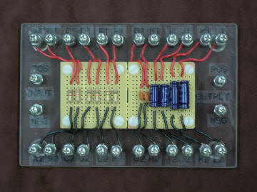
This board is simply six resistors and six capacitors in three different sizes of each. Each component is connected to a pair of simple machine screw posts. As described in Laboratory #6 of the BIO325 manual, students build and test simple RC circuits by connecting components with alligator clip leads, stimulating with a simple battery or square-wave electronic stimulator, and recording voltage or current with a multimeter or PowerLab system. As they progress through the lab students verify Ohm's Law and Kirchoff's Current Laws with resistors in series and in parallel, build and measure current-divider and voltage-divider resistor circuits, build and test a simple RC model of the cell membrane, measure and calculate capacitive time constants, then build and test high- and low-pass RC circuits (a.k.a. frequency-dependent voltage dividers).
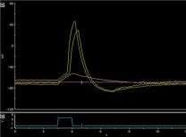
Printouts of the results of using this model as described in laboratory #6 are available online in a poster (PowerPoint format) or upon request from brhoades@wesleyancollege.edu .